In an effort to provide more timely updates, I'm experimenting with a twitter account
Fun fact: a spammer created my account a while back which, although I never formally activated it (ie never clicked on the activation e-mail send to me), somehow got it suspended. Had to jump through some hoops to actually activate it and change the password
Saturday, August 29, 2015
Thursday, August 6, 2015
github restructure
In summary:
Enjoy!
- pr0nscope has been moved from pr0ntools into uvscada. This eases code collaboration on more advanced projects like xy-ray
- All files from uvscopetek repository have been moved to uvscada
Enjoy!
xy-ray x-ray scanner
In some previous posts I talked about getting an x-ray head working, reverse engineering an x-ray sensor, and working with LinuxCNC. In this post I put them all together so that I can take a bunch of x-ray snapshots across an entire PCB. This allows me to more quickly reverse engineer PCBs.

Problem: with my previous work I can take a PCB x-ray at fairly high resolution (see bond wires like above) but the field of view is pretty small. The above x-ray doesn't even cover an entire PDIP-40. How can I see the entire PCB?

These had several desirable properties:
Next I made the PCB holder. The Z axis motor mount makes a convenient anchor point to attach accessories. To actually hold the PCBs I decided to use a PanaVice PCB holder left over from a previous project. This is a great fit as it nearly wedges into the motor mount and is made out of aluminum which is mostly transparent to x-rays (minimal image impact). With a little sanding I was able to sandwich it into the motor mount:

And drill some holes to make it secure:

Which then integrates onto the stages:

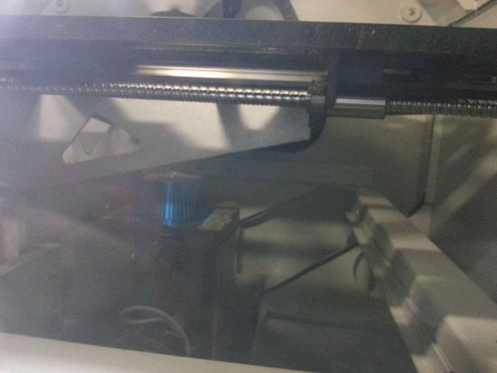
Thinking about the z axis, I recalled I had a spare heavy duty z stage. And guess what? The x-ray head fits onto it perfectly!

Integrating into the system:

In this configuration the stages can't travel their full range but given the low effort this is a great starting point. You can also see the sensor in position.

AXIS would have worked fine but because I was focusing on rsh it was a bit of a pain to switch back and forth. It may be possible to launch AXIS along side linuxcncrsh but I haven't looked into it.
Notice the slopping wiring going everywhere. Lets see what we can do about that...

And started mounting electronics:

A few boards are on standoffs but I'm DIN rail mounting what I can.
I started routing cables and found that the Y power cable doesn't reach. After splicing it to extend it:

And then heat shrinking it to prevent it from snagging and hiding the splice:

Going back to the electronics panel, you'll notice the e-stop button to the right. In production:

Unfortunately I don't have any drills large enough for the button. My step drill got pretty close but not there. I thought about putting it on my milling machine / rotary table but decided that since I only needed to shave off a little that probably wasn't the most expedient (notice I didn't say best) option.
Instead we come to "Mr. Safety" on the left. Although I didn't use a milling machine, I did put an endmill into my rotary tool and mill out the center a bit by hand. This is a terrible idea and you really shouldn't do this for numerous reasons but it did get the job done.
Following that I finished the button with a coat of Dykem Blue. It already had some on there from marking holes and I decided it was going to be less work to coat it blue than to remove the layout fluid.
Filling out the control system:

I DIN rail mounted the BBB onto a Phoenix Contact PCB mount by screwing the case into the PCB mount
There are two power rails:
Like previous systems, a laptop orchestrates the whole thing. At the core is my pr0ncnc which underwent a major, long overdue code cleanup for this project.
Also like previous setups, the x-ray is powered by two Variacs switched through a DLI WPS-7.

For my first scan I grabbed a scrap HDD PCB in arms length:

And you can find the output files here (TODO: stitch, mapify). A few sample images:


Unlike my system, these allow real time imaging, HDR, and some other cool features. Still, I'm sure my garage system costs a fraction of what these beasts go for and is considerably more compact.
There are a number of things I can do to improve scan quality but should be good enough for most projects. The system will get used in the near future for PCB reverse engineering projects.
Got something cool you want scanned? Drop me a line!
EDIT: looks like you can get small x-ray units at industrial auction for 1k. Still, this was well under that and was a fun project

Problem: with my previous work I can take a PCB x-ray at fairly high resolution (see bond wires like above) but the field of view is pretty small. The above x-ray doesn't even cover an entire PDIP-40. How can I see the entire PCB?
Linear stage
Linear stages are great for this sort of project. As I'm moving on the order of inches they don't necessarily need to be high precision. I looked around eBay and a few other places and settled on some stages as HSC. I can't find a picture of the original setup, but something like this:
These had several desirable properties:
- Around the right scan area I'm looking for
- Reasonably sturdy to support PCB weight
- Motors with integrated drivers (MDrive 17Plus). As a plus they are 3.3V compatible
Next I made the PCB holder. The Z axis motor mount makes a convenient anchor point to attach accessories. To actually hold the PCBs I decided to use a PanaVice PCB holder left over from a previous project. This is a great fit as it nearly wedges into the motor mount and is made out of aluminum which is mostly transparent to x-rays (minimal image impact). With a little sanding I was able to sandwich it into the motor mount:

And drill some holes to make it secure:

Which then integrates onto the stages:

Mounting the head
Next I need to mount the x-ray head. Its heavy so this could be a bit challenging. I was originally thinking of making a t-slot gantry so that it would clear the stages nicely. It would be a plus if I could adjust the height up and down but not strictly necessary.Thinking about the z axis, I recalled I had a spare heavy duty z stage. And guess what? The x-ray head fits onto it perfectly!

Integrating into the system:

In this configuration the stages can't travel their full range but given the low effort this is a great starting point. You can also see the sensor in position.
Software
The software development is mostly covered in my previous post. Here is an early integration test with the pr0nscope GUI I use to control my microscopes:
AXIS would have worked fine but because I was focusing on rsh it was a bit of a pain to switch back and forth. It may be possible to launch AXIS along side linuxcncrsh but I haven't looked into it.
Notice the slopping wiring going everywhere. Lets see what we can do about that...
Control system
Onto the control system. In the above picture you can see an aluminum plate to the left of the stage. This held the original indexer board that I decided not to use in favor of standardizing on LinuxCNC. I drilled some holes for standoffs (not super great but sufficient):
And started mounting electronics:

A few boards are on standoffs but I'm DIN rail mounting what I can.
I started routing cables and found that the Y power cable doesn't reach. After splicing it to extend it:

And then heat shrinking it to prevent it from snagging and hiding the splice:

Going back to the electronics panel, you'll notice the e-stop button to the right. In production:

Unfortunately I don't have any drills large enough for the button. My step drill got pretty close but not there. I thought about putting it on my milling machine / rotary table but decided that since I only needed to shave off a little that probably wasn't the most expedient (notice I didn't say best) option.
Instead we come to "Mr. Safety" on the left. Although I didn't use a milling machine, I did put an endmill into my rotary tool and mill out the center a bit by hand. This is a terrible idea and you really shouldn't do this for numerous reasons but it did get the job done.
Following that I finished the button with a coat of Dykem Blue. It already had some on there from marking holes and I decided it was going to be less work to coat it blue than to remove the layout fluid.
Filling out the control system:

I DIN rail mounted the BBB onto a Phoenix Contact PCB mount by screwing the case into the PCB mount
There are two power rails:
- 24V for stepper drivers. It was supposed to be supplied by the DIN rail supply but I am missing a Combicon adapter. For now an external power supply runs it
- 5V from the BBB sets a control line in the stepper motors
Like previous systems, a laptop orchestrates the whole thing. At the core is my pr0ncnc which underwent a major, long overdue code cleanup for this project.
Also like previous setups, the x-ray is powered by two Variacs switched through a DLI WPS-7.
Putting it all together
Viola:
For my first scan I grabbed a scrap HDD PCB in arms length:

And you can find the output files here (TODO: stitch, mapify). A few sample images:


Safety
This system was a bit harder to shield due to the larger volume. However, running the system at 60 kV seems to produce negligible radiation leakage even without shielding and gives pretty good copper resolution. Still, I have lead shielding around the system as an added safety and in case I want to operate at higher voltages.Industrial units
For comparison, here's an XD7500NT industrial x-ray scanner:

Unlike my system, these allow real time imaging, HDR, and some other cool features. Still, I'm sure my garage system costs a fraction of what these beasts go for and is considerably more compact.
Summary
The hardware came together pretty quickly and was mostly built over last weekend. Figuring out how to configure and control the BBB took longer but is a good investment. The integrated MDrive 17Plus stepper drivers make the system quite compact over my previous control systems.There are a number of things I can do to improve scan quality but should be good enough for most projects. The system will get used in the near future for PCB reverse engineering projects.
Got something cool you want scanned? Drop me a line!
EDIT: looks like you can get small x-ray units at industrial auction for 1k. Still, this was well under that and was a fun project
LinuxCNC/Machinekit, BBB, and Python
Background
My original computer controlled microscope ran LinuxCNC on an old laptop:
You can see AXIS running on the laptop to the left along with a scan pattern.
Unfortunately, it was difficult to make this system compact and reliable. Laptops aren't really that great to run real time software because ACPI gets in the way. Desktops can work but they are bulky and still need to be somewhat carefully selected. My Sherline mill compromises by using a mini ATX motherboard connected to a laptop. That way the laptop does all the display, keyboard, and mouse in a compact form factor while running all the real time tasks on a purpose built PC.
But this was still too big and costly to generally deploy. Instead, I made "pr0ndexer" which runs on inexpensive STM32 dev boards. The firmware was written in an afternoon and seemed to work well to get the job done.
Or did it?
After a while one of my motors started to slip. Evidently lack of acceleration was wearing out gears in the linear stage.
Oops.
So I patched up the software with some crude acceleration and production continued to hum along. But still it was still pretty crusty:
- Pulses are generated with sleep statements instead of timer ISRs. Receiving serial characters (or other tasks) messes up the timing
- Only one axis can be moved at a time
Towards the BBB
While this was happening it was brought to my attention that LinuxCNC had been ported to run on Beagle Bone Black (BBB) by the Machinekit. At this point though things were working well enough that I decided not to pursue that.Fast forward to 2015. I'm building more robots and need to decide what the next control system will look like. I decided to revisit Machinekit/BBB which I'm just going to loosely call BBB.
For most of these systems I'm moving some number of stages and doing some sort of image capture. There are two ways the system could be used:
- Run LinuxCNC on the BBB and also do image capture (ie through the USB port)
- Use BBB as a remote control drone and run image capture on a laptop
linuxcncrsh/emcrsh API
When you start LinuxCNC there are a variety of frontends you can use to interact with it with AXIS probably being the most common. One alternative is the rsh frontend which launches a sort of telnet command server instead of a GUI. The developers make no claim that its a robust interface but note that it may be good enough for quick and dirty projects.Seeming to be the easiest way to use in a drone fashion, I started with this. I ran into a few snags though:
- Axis homing takes a long time. My theory is that this has something to do with the way that poll() works (see later) but I'm not really sure
- No position feedback: a command is either running or completed
Python API
Unfortunately while I could get a quick PoC, rsh didn't seem to give enough control for what I wanted to do. So next I tried the python API which is considerably more powerful.Although this API is much more complex, it is well documented and I was able to get it working reasonably quickly. The API is much richer and allowed me to do everything I wanted to (ex: getting position feedback). For example, the Python API is aware of fine points like the target position vs the actual position from servo feedback.
Remote python API
Unfortunately above only works locally (at least as far as I can tell). To use the BBB from a remote system I decided to use XML-RPC since I've used it before and its pretty easy to use. I instantiate a linuxcnc object that looks just like the linuxcnc module. This allows programs written against the normal Python module to nearly seamlessly my remote version.To make it run smoothly I do the following:
- Copy LinuxCNC .ini file to BBB (SFTP)
- Launch LinuxCNC on BBB using .ini file (SSH)
- Copy XML-RPC server to BBB (SFTP)
- Launch XML-RPC server on BBB (SSH)
- Create SSH tunnel from BBB to localhost
- Connect to BBB using XML-RPC client
The core linuxcnc remote interface client and server are here. The wrapper to remotely deploy it can be found here. Here's an example program using the wrapper.
Polishing
I'm using the CRAMPS configuration as a base. This unfortunately has a lot of stuff I don't need and causes it to take a long time to start up. I've started stripping down the config but there's still a lot to strip out (ex: thermal management).I'd also like linuxcnc to launch automatically at start up which probably isn't too hard. I'd also like my config files to get versioned which may just mean I check out the uvscada git repo to the BBB. This eliminates most of the above steps.
XML-RPC has a lot of overhead: it creates a connection for every function call and XML isn't terribly efficient. Fortunately I'm not doing anything super performant so this is probably okay.
Applications
I have several new imaging systems coming online. This project was primary driven by my x-ray scanner:
which I'll do a post on in the near future. I'm also planning on deploying this to existing systems like pr0nscope and k2scope.
Summary
The Beagle Bone Black is a very compact platform to run LinuxCNC from. The rsh API is good for very simple remote control applications but you should use the Python API (or C API) if you need better control. I've provided some wrappers to use the API remotely almost as easily as the local API.For the amount of work put into this it came out pretty good. There's still a lot of room for improvement but its mostly better than my pr0ndexer board. The main disadvantage so far is that the BBB takes several minutes to start up where my board was ready in under a second. For most of my applications this isn't a big deal. That said, I'm eventually going to look into ways to cut down startup time.
Subscribe to:
Posts (Atom)
