Sunday, December 5, 2021

Migrating from kernel to gstreamer drivers

I've been asked a number of times why I stopped developing Linux kernel camera drivers and instead bind them to gstreamer and/or write userspace libraries. This article takes my journey from gspca_touptek to gst-plugin-toupcam as a case study.

TLDR:

  • Quicker model support
  • Community better structured to accept contributions
  • Better cross platform support

Linux kernel

Everyone told me the "proper" way to support a camera is to get it upstreamed in the Linux kernel. So let's give it a go!

First, getting a driver PoC required breaking their protocol obfuscation and writing a driver. While I can do binary reverse engineering, there are those much better than me and fortunately I got some help from Ben Byer. With his help I was able to make a utility to break the encryption and develop a PoC userspace application. This process was a big motivation to develop my usbrply USB reverse engineering tool / framework which ended up being my most popular open source project once I cleaned up the documentation.

Anyway, getting it merged was a high touch process involving changing APIs and tweaking to coding preferences. This was especially frustrating in some instances where I copy and pasted existing code that no longer conformed. This is all reasonable given the scale of a project like the Linux kernel, but it discourages smaller contributors that don't do this as their full time job.

I wanted to use a nicer camera but was pretty tied to MU800. In fact I had even already written a driver for an MD series camera and even received some patches for MU300 but wasn't excited about going through the process again to merge them in. Even if I did the work it would take a long time to filter through distribution channels to Ubuntu and such.

There were also practical problems. The color balancing scheme I had (via gspca?) is green gain, red balance, and blue balance. This meant that it was hard to have accurate blue channel control when you had low green gain and other quality issues that didn't allow using the full camera capabilities. In general I really need direct setting (register) control to get good quality images. However, kernel devs are strongly against allowing raw I2C access and instead want proper controls implemented for everything which greatly increases the complexity of the project. Ultimately I use a small patch to hack around direct RGB control, the most critical issue.

gstreamer

But wait, do I actually need a V4L driver for my use case? What are my requirements? Ideally:

  • Available through gstreamer on Linux
  • Support MU800
  • Support future touptek cameras like E3ISPM series
  • Plus if it runs on ARM like Raspberry Pi
  • Plus if its open source
  • Plus if its cross platform

Could I make a gstreamer plugin instead? Well I could make a userspace driver as I did anyway sometimes prototyping the kernel drivers. But touptek also publishes an SDK (C and Python bindings).  I took a look at the SDK and quickly got some images out in Python. Could I pipe that in somehow? It's not open source, but would satisfy everything else.

I took a look at getting started with gsreamer development but ran into a few snags. I can't recall specifics, but they had a quick start tutorial that partially worked but didn't get me far enough to actually get started. I think it was a combination of not finding an example on how to make a video source and issues related to Meson. Ultimately I found someone on Upwork that helped me to get a PoC to captured a single image as a C gstreamer plugin.

Once I had a PoC I was able to iterate for what I really wanted. At this point I was communicating with gstreamer developers for both my plugin development and userspace app. They were super friendly and helped me when I ran into problems. Additionally, while Linux has a monolithic plugin repository, gstreamer has an interesting approach with several classes of plugins loosely like:

  • good: good quality code, correct functionality, our preferred license 
  • ugly: good quality and correct functionality, but problematic distribution
  • bad: fundamental issues (ex: licensing, stability), but its useful enough to be kept

This means they can accept things that might otherwise be rejected by putting it into the right bucket. 

Additionally they are more accepting of out of tree plugins. This significantly reduces my development overhead as:

  • Friendlier to use existing system software instead of compiling gstreamer from source
  • I can make my own small git repo instead of merging into mainline
I also found other communities maintaining industrial camera gstreamer plugins and had talks to them about the merits of merging it into their repos vs keeping my own. They were open to me merging things in but, at least at the time, it was better to have more direct control to keep development moving quickly.

Finally, gstreamer sometimes retweets gstreamer related things I post. Even though I didn't merge these patches into mainline, its a nice acknowledgement that I'm still part of the community.

Final thoughts

Both approaches have their merits but for me gstreamer has been a clear win. Its sad I've dropped my other kernel patches but the ROI for me to get them merged is too low.

I've also been told its possible to do a userspace-v4l bridge, but haven't looked into this much. My instinct says that direct gstreamer support is better for my use case.

Sunday, January 3, 2016

The McMaster-Car

Sadly, I scrapped my 1994 Ford Taurus station wagon some months ago.  This is a tribute showing how I pimped my ride, its demise, and how I abused it before it finally got crushed.

Rolling in style


At its inception it was a pretty luxurious car that included stuff like a console mobile phone.  I looked into hooking it up and, unfortunately, analog cell service had been discontinued by 2013 when I got it.


My mom proudly displayed her country-western line dancing enthusiasm on her license plate cover.  However, she forgot to remove it when she gave me the car.  While I wouldn't put it on, I wasn't going to take it off.  People loved it and gave me lots of funny comments.

One day I was eating lunch with my boss and mentioned that what my car really needed were some flames.  He thought for a second and mentioned that he has some kicking around somewhere.


I came out to lunch a few months later and discovered my car now had some sweet flames!

But we can do much better.


Laugh at the station wagon all you want, but it still sports a 3.0L V6.  Flames are good, but what a muscle car really needs...


Is a skull shifter for its automatic transmission.  This actually was a bit of work to install as the original shifter was pressed on.  I still get Jeggs magazines to this day.  Trivia: I now use the skull to test satellite cameras.


But more flames wouldn't hurt.  How about a flaming Rat Fink antenna ornament?  It was a close call between him and a flaming eyeball.  This was the most expensive upgrade I did, running me about $20.


And wouldn't those hubcaps be better with some bling?  Nothing a little gold spray paint can't fix.


Of course, I'm only referring to the hub caps it still had.  Maybe I should have sprayed the rim gold?


Not that the emergency brake release was doing much better.  Nothing a little bicycle wire couldn't fix.


But the fuzzy dice didn't care.  I originally had them on the rear view mirror (per tradition) but found them too distracting.  I relocated them to the dashboard where they occasionally fell apart.


There were quite a few other upgrades I considered but never got to.  For example:
  • Piston door locks (like this
  • Nitrous (more on that)
  • McMaster-Carr bumper sticker.  Someone actually contacted them for me trying to get one to no avail (could make one easily though)
  • Racing stripe
  • Hood shaker
  • Spoiler

Its time to go

With over 200,000 miles, the car was worth maybe $800.  I was constantly working on it and, for example, recently replaced nearly the entire coolant system (hoses, radiator, water pump...).


I got rear ended and their insurance gave me $1100 but didn't total the car!  The car is a bit of a tank and really only sustained minor damage to the rear bumper.

At about the same time the government offered me $1000 to get the car off the road.  Now with $2100 for an $800 car, it was time to move on.

But not before I have some fun.  I looked over the gov program and more or less as long as the car barely worked I'd still get the money.

I went out to a large open area with a bud from work and started with some donuts.  Then I set the emergency brake and drove around for a bit.  I also slammed on the brakes as hard as I could (regular and e-brake).  Unfortunately the e-brake doesn't have much stopping power and so it only gently brought the car to a stop.

My favorite though was doing a burnout by revving the engine up in neutral and shifting it to drive.  The engine suddenly engaged and spun the tires so fast that smoke shot out.

There's a supermarket near me with a low dip into the parking lot.  The car has really low clearance so I have to go really slowly to avoid scraping it.  Of course, this time I went up there and floored it out of the parking lot, probably showering sparks with the impact.  I was somewhat surprised that the car still worked.

The steering wheel wiring harness had already fallen off and I really wanted to hotwire the car.  However, I wasn't confident I could do it without damaging the car so ultimately passed.

I really wanted to do NOS but everyone warned me that, with the engine's age, it would very likely destroy the engine on the first go.  Too bad as this would have been great for Wednesday Night Drags.

I also looked into demolition derby which actually wouldn't have been too much work (fuel cell + minimal cage).  I also wanted to shoot out some of the windows but didn't make time for it.

Gone


Ultimately though it found its way to the scrapper.  I wanted to drain the engine oil and see if it could make it there (10 miles) but my dad pleaded with me not to try it.


I seriously considered getting a hearse to replace it ("Last Ride" style) but ultimately decided on a 2006 RAV4.  By a hilarious twist of fate, it also had a dance themed license plate cover that was even stronger than the Taurus' (that my mom had also taken back by this point).

I still dream about getting a rat rod or a tank.  I actually found a really good local deal on a Warthog APC but unfortunately don't have a place to put one. Along with the SBX-1 and Sea Shadow (RIP) of course.

Friday, January 1, 2016

Machining K2 microscope Z adapter

A short post on installing a crank wheel onto my confocal microscope.


Problem: my K2 IND system Z axis is painful to move (ie focus on chips).  The original servo drive relies on a computer controlled rotary switch for user focusing.  This would take a bit of work to setup and I had problems getting the servo working reliably.  I'm fairly certain I just need to buffer the encoder signals, but at this point I just want to KISS.

My first solution was to use a power drill but that was a bit messy.

Lets do something a bit more proper.  I selected a handwheel off of Amazon to replace the motor and bought some 1" aluminum stock to make an adapter.  The stock needs two critical cuts:
  • Outside diameter 0.472" to fit the wheel
  • Inside diameter 0.5" to fit the microscope
I made some rough length calculations and cut the aluminum to length.

Microscope diameter


I put the stock into my lathe and quickly re-discovered why I don't use the three jaw chuck: it has trouble holding material even when tightly clamped.


So I switched to a four jaw chuck and centered it using a dial indicator (sort of visible at right).

Its generally easier to clamp large parts, so lets make the inner diameter cut first so that, when its flipped around, its easier to hold.


First I center drilled the stock


Then drilled it out as large as I could.  This is quicker than using a lathe tool and allows the lathe tool to actually fit inside.


Now I switched to a tool bit to set the final diameter.  I cut it to about 0.505" so that it slides on easily but is still pretty well centered.


I used calipers to check the size as I went.  After some cutting the hole is correctly sized.

Microscope set screw


The microscope side has a large flat, so a set screw is a good choice to hold it in place.


I started by clamping it in my milling machine and milling a flat so that I could drill a hole more precisely.


Next I used a center drill to start the hole.


10-32 seemed a good size so I selected a #21 drill bit and had at it


And tapping (carefully!)

Crank wheel diameter

Although the crank wheel has a key, I figured it would be simpler to press fit it on.  So my plan was to machine it to very close tolerance and press it on.


Re-attaching to the lathe and centering.


Starting to cut


Lots of cutting!


Due to a measurement error (maybe overshot during finishing?) it was a close fit but not snug.  Do I need to scrap the part or can I recover?


Its pretty close.  Maybe I can squeeze it in my vice?  Hmm no...wasn't enough.


Lets get something with a little more oomph.


Seems to have done the trick.


Tried to press it directly but it was clear it was going to go off center.


So I added some supports.


Which did the job.


Viola!  Everything fit together as expected and the crank turns smoothly.  Now I can easily focus on ICs and not have to use frustrating hacks to use the microscope.


Saturday, December 26, 2015

Characterizing the SBM-20 Geiger-Müller Tube

Above: SBM-20

Above: other SBM-20 design?  I thought this was STS-5 originally but its clearly labeled SBM-20

This article shows how to characterize a GM tube as well as how to build a Geiger counter out of basic lab equipment.

I've been trying to get a neutron detector working to show my fusor works.  Unfortunately its been the most time consuming and frustrating part of the project.  After overpowering and subsequently killing a $50 He-3 tube, its time to practice on something similar but less expensive: the Geiger-Müller (GM) tube.

Surplus from Russia, the $10 SBM-20 is the most common radiation tube on the surplus market (along with the similar STS-5).  Despite their low cost they are well built and provide crisp signals.

While I'll quote Wiki a few times in here I've mostly been reading PANDA.  PANDA focuses on neutron detectors but a lot of it is based on conventional tubes.  In fact, I think the Wiki page has a number of incorrect statements about energy resolution and such (or at least misleading if its a terminology issue).  I'll write my congressman.

Theory

GM tubes are filled with low pressure gas at high voltage.  They essentially operate as a triggered spark gap: when a high energy particle excites the gas it momentarily produces electric current.  This current can be averaged to determine pulse rate or individual events can be counted.

While Geiger counters operate in this spark gap mode, its possible to excite other modes.  In more detail, here's a theoretical GM plot from Wiki:

In the so called "ion chamber region" no amplification occurs and thus only very small amounts of current => weak signal is produced.  As the voltage is increased, the tube enters the "proportional region" where output current is dependent on input energy.  That is, a 100 keV gamma rays induce less current than a 1 MeV gamma rays.

As voltage is increased further, amplification saturates to form the "Geiger region".  Geiger counters operate here since it produces strong, consistent signals that don't vary much across voltage.   This makes units less sensitive to manufacturing tolerances and aging that bring components out of spec.  All particles now produce identical looking pulses regardless of energy.

Thin metals block alpha particles.  Therefore, metal walled GM tubes like the SBM-20 only detect beta and gamma particles.

SBM-20 specifications

The SBM-20 has the following key specs:
  • Minimum Anode Resistor: 1.0 M
  • Recommended Anode Resistor:  5.1 M
  • Recommended Operating Voltage: 400 V
  • Operating Voltage Range: 350 - 475 V
  • Initial voltage: 260 - 320 V
  • Plateau length: > 100 V
  • Maximum Plateau Slope: 10 %/100 V
  • Minimum Dead Time at 400 V: 190 us
  • Life (pulses): > 2e10
For these tests I'm using a 4.7 - 4.8 M resistor (what I had on hand).  This is about 8% off of the characterized value but well within the recommended range.

Counting

Slightly simpler, I initially counted pulses instead of measuring current.  Schematic:


Specifically I'm using:
  • SBM-20 GM tube
  • Ortec 456 HV power supply
  • Agilent 54622D scope (floppy drive FTW)
  • HP 53131A counter
  • 10 uC Cs-137 source (Spectrum Techniques, 2015)


Instead of adjacent, I placed the source 1 inch from the tube to make the experiment more repeatable.  This minimizes effects small movements have such as placement position and vibration.

I started with characterizing startup voltage.  I found SNR approaches 1 at about 240 V:

Above: 240 V


Above: 250 V w/ ~10 mV signal

This is roughly consistent with the datasheet (Initial voltage: 260 - 320 V).

Now with a signal I setup the counter threshold.  I found that the noise floor is about 3 mV across all voltages.  If I shielded the probes and such properly it would likely go down.

Anyway, the counter requires 5 mV steps so I set the threshold to 5 mV (rising edge).  Unfortunately, I found that, according to the scope, the counter doesn't trigger until 15.3 mV (ie has 10 mV offset error).  As a result, the first recorded count is at 270 V despite the scope seeing counts at 250 V.


Counts increased roughly linearly up to about 1200 V (note: I took fewer samples later in the graph artificially making it appear smoother).


After that pulses start ringing, drastically increasing CPM.  More on that later.


As I thought the GM tube was going to give out much earlier I didn't beef up the resistors to account for the extra HV.  At 2000 V, the current limiting resistor failed (not too surprising) which then caused the sense resistor to fail (above).  Resistor damage:
  • 4.7 M => 2.1 M
  • 4.7 k => 486 k
The 4.7 M resistor was replaced with 4x 1.2 M (4.8 M) and the 4.7 k resistor resistor was replaced with a new unit.

Measuring current

A single particle imparts a varying amount of charge.  However, when averaged over time we get electrical current which is easier to measure.  Along with our sense resistor, adding a capacitor in parallel forms an RC filter to smooth out the current, making it easier to measure.


Very similar to before with the following tweaks:
  • 4.7 M resistor => 4.8 M as 4x 1.2 M
  • 4.7 k resistor replaced
  • 4.7 uF capacitor
Note RC = 4.7e3 * 4.7e-6 = 22 ms with f ~= 3000 => T = 0.3 ms.  That is, the capacitor takes much larger to discharge than the rate pulses are coming in.

I wired it up and placed the source nearly against the GM tube so that it provides a large signal.  This is what I got:

Where:
  • Red lines: min/max recommended operating voltages
  • Green line: recommended operating voltage 


This is basically the rightmost third of the Wiki image with an extra inflection.

The red line above is where continuous discharge begins.  By 2000 V it looks like it was starting to saturate and may have leveled out if I kept going.

The green line marks the end of the plateau region.  While the datasheet says that its approximately 350 - 475 V, 600 - 1100 V looks better.  In particular, the curve is pretty steep at 350 V and therefore not ideal to operate at.  Even with the recommended current limiting resistor I'm guessing that it would not have evened out yet.  Possibly due to tube age?

Regardless, it demonstrates power supply stability importance: no matter operating voltage, current (rate) depends on voltage.  If you want stage readings you must supply a stable voltage.

GM region slope is about 3.5 count / V.  At 600 V I got 1758 counts => 100 *  (3.5 * 100) / 1758 ~= 20 % / 100 V vs datasheet spec of 10 % / 100 V.  However, at 1000 V I got 3153 => 100 * (3.5 * 100) / 3153 = 11 % / 100 V, roughly in spec.  Lets call it 15% / 100 V.

The area to the left of the green line is likely the proportional region.  Given the relatively high noise in my setup, I was unable to observe the ion chamber region.

Continuous discharge

Wiki says "If the applied voltage is higher than the plateau's, a continuous glow discharge is formed and the tube cannot detect radiation."  I was not able to get a continuous glow discharge to form (strong quenching agents?), but I was able to demonstrate that the tube can detect radiation far above the plateau region.


Above: unstable at 1200 V

At around 1200 V I started to see the pulses "ringing".  This explains the increased counts at higher voltages observed earlier.


Above: unstable at 2000V

As the voltage is increased further, the rings appear to ring themselves and thus take much longer to stop.

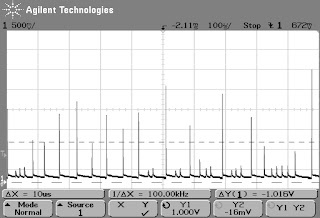
Above: 2000 V w/ no source

Even without a source a considerable number of pulses are produced.  However, a valid count can be generated by subtracting this out.  I first set the counter to 5.125 V (max threshold) to filter out most noise.  With the ~3000 CPM Cs-137 source I got about 33765 CPM.  When it was removed I got 30670 CPM, a difference of 3095 CPM.  Additionally, when I added a strong Am-241 source it shot up to 49879 CPM.  Therefore, despite the tube being quite noisy at 2000 V its still usable.

Of course, this range is still quite bad for tube life (2e10 events).  Assume all events degrade the tube equally.  At 2000 V I got 2486306 CPM ~= 2.5e5 CPM (mostly background).  This yields 2e10 count / 2.5e5 count/min = 55 days operation.  While this won't immediately kill the tube its unnecessarily stressful.

Dead time

Dead time is the time after a pulse that you can't get another pulse.  I suppose I could have looked to find the closest pulses but, in general, this is difficult to measure.  As a first order approximation, lets consider dead time equivalent to pulse width.

Dead time is a function of voltage.  I didn't measure it specifically, but here are some examples to illustrate.


Above: 250 V.  Rise to peak: 10 us.  Rise to decay inflection: 30 us


Above: 400 V.  Rise to peak: 0.75 us.  Rise to decay inflection: 1.75 us


Above: 1200 V.  Rise to peak: 0.25 us.  Rise to decay inflection: 0.75 us

As voltage increases pulse get both higher and faster.  Pulse rise in 10 us at 250 V, 0.75 us at 400 V, and 0.25 us at 1200 V with similar gross decay times.  However, it always takes around 100 us for the signal to fully recover to its original DC value.   Possibly due to stray capacitance or slower positive ions recovering.

The main takeaway is that higher count rates are possible at higher tube voltages as long as you don't enter continuous discharge.

Reversing

The tube is clearly marked with a "+" on one of the terminals.  But theoretically it should collect charge on either terminal.  So what happens if you reverse it?

At +400 V I recorded 3068 CPM.  At -400V I got 1381, about 45% of the + reading.  When I removed the source altogether I got 9 CPM.  So clearly its working as a detector, albeit less efficiently.


I tried to take current measurements and by 700 V spikes were already occurring.


By 900 V the signal was unstable as they no longer settled to a steady state.  Maybe oscillating with the capacitor? 

Overall appears to be less efficient and works under a much narrower range.  Presumably GM tubes are optimized for positive voltage though so maybe it could be improved a lot if you intentionally tried to design a negative center GM tube.  In any case, the biggest takeaway is that under standard 400 V operation the tube works.  This is actually unfortunate as you might not notice you installed it backwards (mechanically possible).

Pulse height variation

I didn't actually try spectroscopy, but I did measure pulse height min/max.  If these are related to energy deposited, this should roughly indicate energy resolution capability.

Measured from the usable tube range: 250 V to 1100 V.  As tube voltage increased, the height difference between the lowest and highest pulse also grew linearly.  Once again, an actual spectrum would be required to see if this difference is actually useful.

Summary

Datasheet attributes claimed vs what I measured:
  • Recommended Operating Voltage: 400 V
    • Optimal: about 800 V
    • Recommended is not the same as optimal, but 400 V was on the edge of plateau region
    • Probably enough for intended applications
  • Operating Voltage Range: 350 - 475 V
    • 250 V -  1100 V
    • Lifetime concerns at higher voltages?
  • Initial voltage: 260 - 320 V
    • 250 V
  • Plateau length: > 100 V
    • > 600 V
  • Maximum Plateau Slope: 10 %/100 V
    • 15 % / 100 V
  • Minimum Dead Time at 400V: 190 us
    • Wouldn't maximum dead time be more useful?
    • 100 us measured?
Noting:
  • Old tube
  • ~4.7 M sense resistor instead of 5.1 M

Future work


Its difficult to dispute the datasheet plateau reading since I didn't run with exactly the recommended resistor nor with a fresh tube.  To this end I'd like to re-run the current sweep with a fresh tube using a 5.1 M resistor.

In any case, I'm going to characterize a larger tube and tweak the setup to get the ion chamber region.  If instead of using a small sense resistor, I capacitively couple the HV side I should get a much stronger signal.  I also have a CAMAC high voltage power supply that should help me automate sweeps (poor / no documentation though).

For new tests, first I'd like to create some SBM-20 gamma spectra.  I'd also like to estimate efficiency.  Finally, might be interesting to saturate a tube in an x-ray machine and see if anything interesting happens.

Suggestions?  Want to send me radiation stuff?  Drop me a line

Until next time