I played a bit before with using a lapping machine by "hand". Here's a picture of the setup:
Basically I press a die against the lapping wheel with my finger and occasionally refill the colloidal silica reservoir (white stuff with stopcock) as it runs low.
See tutorial I wrote a bit back for details.
However, this method tends to give an uneven finish that's okay for looking at a specific part of a chip but not good/reliable enough for full chip images. This is pretty typical (RSA SecurID):
See the rings? That's optical interference showing more polishing towards the edges than in the center. There are some things that can be done to improve this (ex: use HF to eat down more initially, change speed/pressure) but ultimately it lacks repeatability. For example, depending how tired I am my interpretation of pressing "soft" and "hard" might change.
This post is about my experiences trying to start with low cost lapping
approaches, the problems I encountered, and how those problems were
solved as my system and techniques developed.
Nowadays most chips use lapping machines to very precisely polish chip layers during manufacturing. These lapping machines are quite sizable in order to work on full sized wafers. This tends to make them both more expensive and larger than I can afford.
But what tabletop lapping machines? Vendors such as Logitech make very high quality compact units. Some other brands include Ultratech, South Bay Technology, and MTI Corporation. Most of the fixtures/jigs that go with them are quite expensive, typically starting at $1000 and can get quite expensive (there is an eBay seller asking $17,750 for a new old stock Logitech fixture). MTI seems to be the price-performance leader and sells a small relatively low priced jig that I was able to get my hands on, the
EQ-PF-3H1W2:
Its really designed for getting an arbitrary flat surface for
metallurgical applications, but I figured that I could try to coax it into doing parallel polishing. In any case, it has three main components:
- Sample holder (upper right): keeps samples at right angle to lapping plate and guides weights against samples
- Conditioning ring (bottom): helps smooth out lapping solution and filter out debris
- Weights (upper left): to control pressure against sample
First problem: how to hold the sample. It didn't come with any instructions but looking at it and their website products it seems you are supposed to put a cylinder in at least one of the holders and tighten the setscrew until it can barely move. Weights can then be placed on top to vary pressure as needed. Its designed for 1" samples but since the teardrop causes the cylinder to wedge against the side I imagine the exact diameter isn't critical
MTI's website seems to suggest two options for holding samples:
- Press sample with powder into a cylinder
- Pour epoxy into (silicone?) holders with sample
These are well suited for metallurgical applications as both of these can accept arbitrary shaped samples. However, the first option is out as dies are fragile and might not survive pressing. The second option is plausible but I'm a little put off by the setting time. A third option is to affix the sample to a metal cylinder as done in parallel polishing fixtures. This turns out to work better but we'll explore other options first since I didn't have suitable materials on hand.
The very first thing I tried was to cast the samples in PLA. I couldn't get it fluid enough to do any good. I didn't try hot glue but it might have done better. Looking for something less viscous, wax is cheap and quite fluid when hot. The plan is to omit the conditioning ring (raises the jig slightly) and lap directly against the plate. No control over pressure and such but under "try the simple solution first". Getting ready:
But what to pour it into? I didn't have anything 1" diameter and was still concerned about it rocking about. So...why not pour directly into the lapping jig? Worst case I melt the wax out. Bottom surface is a solid Teflon sheet for easy release. Lets go! Ready to pour:
And poured:
Hmm...its wandered off center a bit. Not necessarily a problem but also wax crept under it and is now blocking the chip surface. Lets run it on the machine anyway:

A few things to note. First, I don't have a "slurry pump", the device that recirculates solution that spins off the wheel. Instead I have a collection bottle (not shown) and occasionally swap it with another bottle that I use to feed the reservoir/stopcock above the machine. Second, I don't have a real "York support", the piece that supports the jig as it rotates on the machine. There is a small bracket on the side of the machine that was probably intended for the slurry feed (or looks so from the complete unit pictures I see online at least) that I'm supporting the jig with. The point is its not intended to take a load like I'm doing. Still, it held up decently well. I did have to weld a nut onto the threaded rod in order to get things really tight. Chemistry clamps hold everything else together. I originally had the dripper on the same support as the jig but the jig got moved around too much and so ended up just suspending it from a ring stand off to the side.
Additionally, the cast iron ring clamp I made the support out of wasn't quite big enough. Cast iron is easy to break so I figured I'd just snap it and weld it at an angle. I'm not very experienced with welding, but it seemed that heating it up really weakened it. Eventually I just ran a bead over it on both sides with a MIG welder to completely reinforce it with steel.
Finally, as the wax cylinders don't freely move up and down I can't use the conditioning ring. This would have helped to even out the lapping solution and remove particulate.
I don't recall the first round of wax lapping really going anywhere...some combination of the wax being slippery and slightly recessed meant it didn't wear away very quickly. Not easily defeated, it seemed time to add a weight to try to keep it more level and closer to the surface. Some reading I later did suggested that putting acetone down may have been an effective way to fend off wax. Back to the original idea, ready to pour:
Poured and cooled:
That's a nasty bit of thermal expansion/contraction. As the way cooled it really receded from the walls. Hopefully the bottom looks better:
Nope! It still drifted off to the side and looks about the same.
Done playing with wax, I had some West Systems epoxy lying around leftover from some fiberglass work:
I found the hardener in the trash at school. Unfortunately it is not off the shelf type but I was able to e-mail the company for the MSDS and cross-reference it to get a rough idea of mixture proportion and curing time. Anyway, IIRC it takes 24 hours or so to cure so its not nearly as expedient as pouring wax. Some people sell 1-2 hour epoxy that would suite it much better if I got more serious about this method (ex:
Tedpella 2 hour epoxy). So I mixed some hardener and epoxy together and...uh oh. It put off more heat than I was expecting and setup solid in less than a minute. Some beaker cleaning later, I this time measured the actual volume needed:
And more quickly poured it out:

Also owing to the large stainless "heatsink" it didn't setup nearly so quickly for better or worse. The next morning I checked it out:

Although better than the wax casting, it still had a thin layer of epoxy over it. I may be able to do things to improve this but my feeling says that epoxy casts are better suited for odd shaped objects where the exact polished surface isn't as important. Also the wells were not setting up at the same rate, likely the hardener viscosity causing it to not get distributed as evenly as I was hoping. Although I decided not to lap it, I had put a thin wax coating on the side walls and was able to push them out without too much trouble.
Next idea: can I cast the dies into lead fixtures? Surface tension should prevent it from going under and the pressure should help keep it level. I just happened to have access to some casting equipment:
Starting with a simple cast:
Gave this:
The die fell out! Decided to try to just glue it in place and press it against a flat surface:
And it was ready to hit the lapping machine. Note there is a fundamental difference between this setup and the wax castings: the lead casting/weight is free to slide (when properly tensioned) in the fixture and apply pressure to the die. The other castings grabbed onto the side of the fixture and did not slide up and down. This also allows me to use the conditioning ring.
But this ran into problems quickly. With only one weight in there the jig swings inward to reduce friction (outer diameter spins faster => more force). I cast some matching forms and got it to spin reasonably easily,
short video here. I can't find any pictures of the results, it must have been either not level enough or too far below the surface to do anything at all (I'd lean towards the latter).
Next I added a nail on top to try to weight it down a little better. I used a small glob of epoxy to try to really keep it in place. Ready to pour:
During actual pouring there was a weight on the nail to really hold it in place. Came out reasonably good, much better than previous casts at least:
However, the machine now spun somewhat unevenly as, the nail aside, the casting was slightly different weight causing a pressure difference. I was able to smooth it out but after a bit of fiddling with things suddenly sparks and magic smoke violently shot out the machine! When I took it apart I discovered the motor controller wasn't too healthy:
Pretty toasty but fortunately KB controls still sold them and I was able to get a replacement. I went with the larger amperage model to try to make it more durable but
this might not have been a good idea as the minimum speed is now
higher.
Unfortunately, the root cause (other than that the machine didn't have any fuse protection...) was either due to temporary stalling or possibly due to damage in the motor. Getting the motor open is non-trivial though as there's an arbor pressed onto it. I didn't have a proper gear-puller for it but I had something close and was able to jurry-rig some bolts to get the job done:
Once apart I could see that the motor had commutator arching:
I took some resistance readings and things didn't seem too bad, maybe it just needed to be cleaned up. One coil was open however:
If this had been caused by just one stall it could potentially be soldered and the motor salvaged. Although I probably should have taken more resistance readings at this point, I had just gotten a benchtop lathe and wanted an excuse to use it. Turned the commutator down:
And then took some more detailed resistance readings but they didn't look good. Further inspection showed that there were more overheated windings:
Enough bad things at this point that I realized the motor needed to be rewound or scrapped. As this was very labor intensive, I instead went with getting a replacement motor despite that it cost as much as I paid for the machine.
I made two other improvements. First, I installed a 2 amp fuse (1/4 horsepower motor => about 2 amps @ 115 VAC). Second, installed a better support bolted directly to the bottom plate:
Ready to roll again. Ultimately not a complete loss as I now have a better mast and the motor runs smoother. Also while I was at it I replaced the polymeric pad and backing plate.
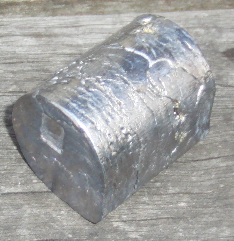
Getting back to work, I was done with the lead castings and wanted to try out using the stainless. First problem: they aren't cut terribly bad but aren't straight:
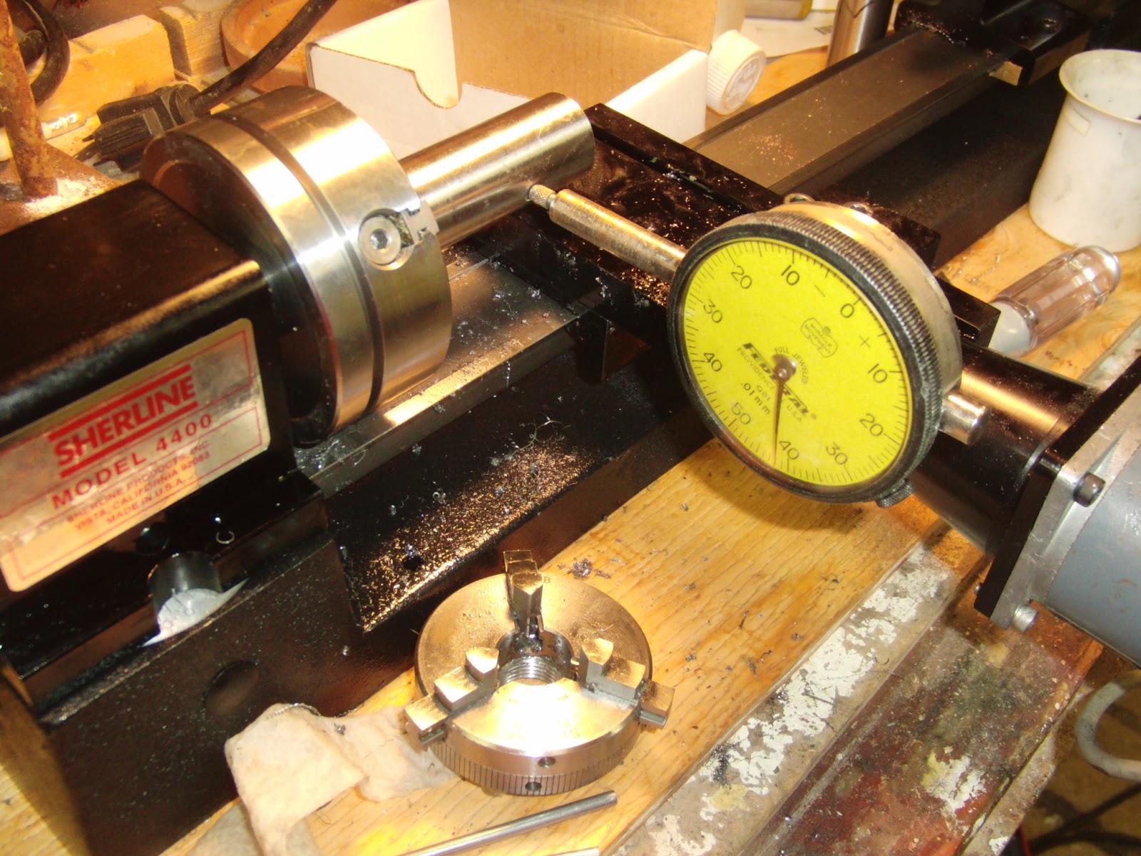
See those slight curves on the end? I think its from their saw slipping around until it bit into the rod. From some combination of this and the 2 inches that it stuck out, using the miniature 3 jaw chuck on my desktop lathe was problematic as it only had a very small flat area to grip. Fortunately, I found that the 4 jaw chuck could hold it pretty good at the expense that I had to align the work:
I had to make very shallow cuts (0.001" or so, carbide bit) but each pass was reasonably quick and it worked out in the end:
But we aren't done machining yet. The previous setup wasn't automatic as I had to keep filling the CMP solution slurry tank manually. To achieve automatic polishing the system needs to be able to run unattended for longer periods of time. Professional systems typically use peristaltic pumps. I sort of had a peristaltic pump but there were two problems:
- The motor was completely burned out but I could turn it by attaching another motor. This is not a blocker but is very inconvenient to use
- I don't have usable tubing
This is my pump head, Cole-Parmer Masterflex 7015:
IIRC I found it in the trash at school along with the burned out motor. Some research showed that L/S 15 tubing would work and I ordered 50' of new old stock Neoprene tubing:
Surplus off of eBay from Hershey's Chocolate USA! Anyway, to solve the pump motor problem, I did have another peristaltic pump motor with the same bolt pattern but the shaft length was very different:
Notice how the slot is visible on the right unit but recessed on the left? Fortunately this was reasonably easy to cut down on a milling machine (sawed off unneeded shaft laying on top to show original size):
I had to go very slowly as there isn't much shaft to hold on. Integrating everything together:
Liquid pumps from a tank on the bottom through the peristaltic pump and drips out from a clamp held by the mast attached to the machine's base plate. Liquid drains into a hose coming off of the machine and recirculates. At some point I'll add a filter but for now I just rely on tank settling to remove bulk particulate.
Getting the fixture ready:
Most lapping guides recommend CA glue or wax for easy sample removal. I used epoxy as I didn't have any CA glue on hand and didn't want to worry about wax coming off at least during first tests. Learning from earlier on how important it is to balance the fixture, all three wells had an identical sample. Put on very small globs of epoxy and then let set under the fixture weight:
I quickly realized that using only one setscrew per well on a cylindrical sample still leaves a lot of play. The other things I tried didn't have this problem since they were cast into the full teardrop shape. Concerning but best to just try it out and see what happens. Lapping:
Here's a
short video of it running. I ran it at reasonably high speed (maybe 180 RPM?) in part because I was short on time. This was about the limit to stop slurry from splashing off. This was aggravated by the new motor which is slightly higher, enough to make the splash guard much less effective.
Once the machine stopped I was at a new problem: the samples on the jigs are too tall to fit under my microscope. Solution: raise the microscope:
Here's the first sample:
Definitely a step in the right direction but not very level. The polish is also much smoother than anything I got with the finger method before albeit not as level. Not sure how obvious it is in the above picture, but this chip has very nice standard cells. Anyway, the other two were much worse:
The left side of the die is unpolished and the right side is gone with a very sharp transition in the center. The third chip is very similar to the second.
So what are the steps for moving forward? If this jig is going to be useful for parallel polishing I need to find a way to keep it more level. However, I also just acquired higher end equipment so future work will most likely focus on that instead.